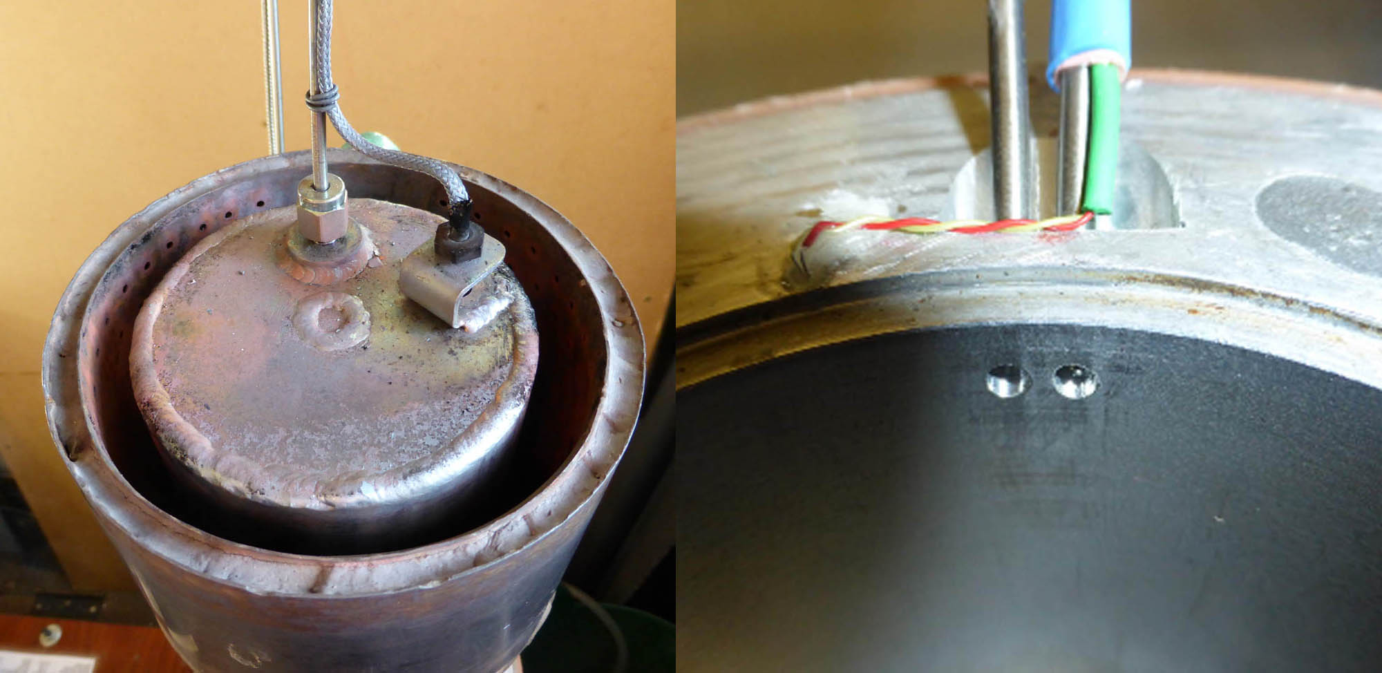
| Hot cap with pressure take off and thermocouple | Inverted view of cold end pipes and thermocouples, one in gas area the other on the water jacket outside. |
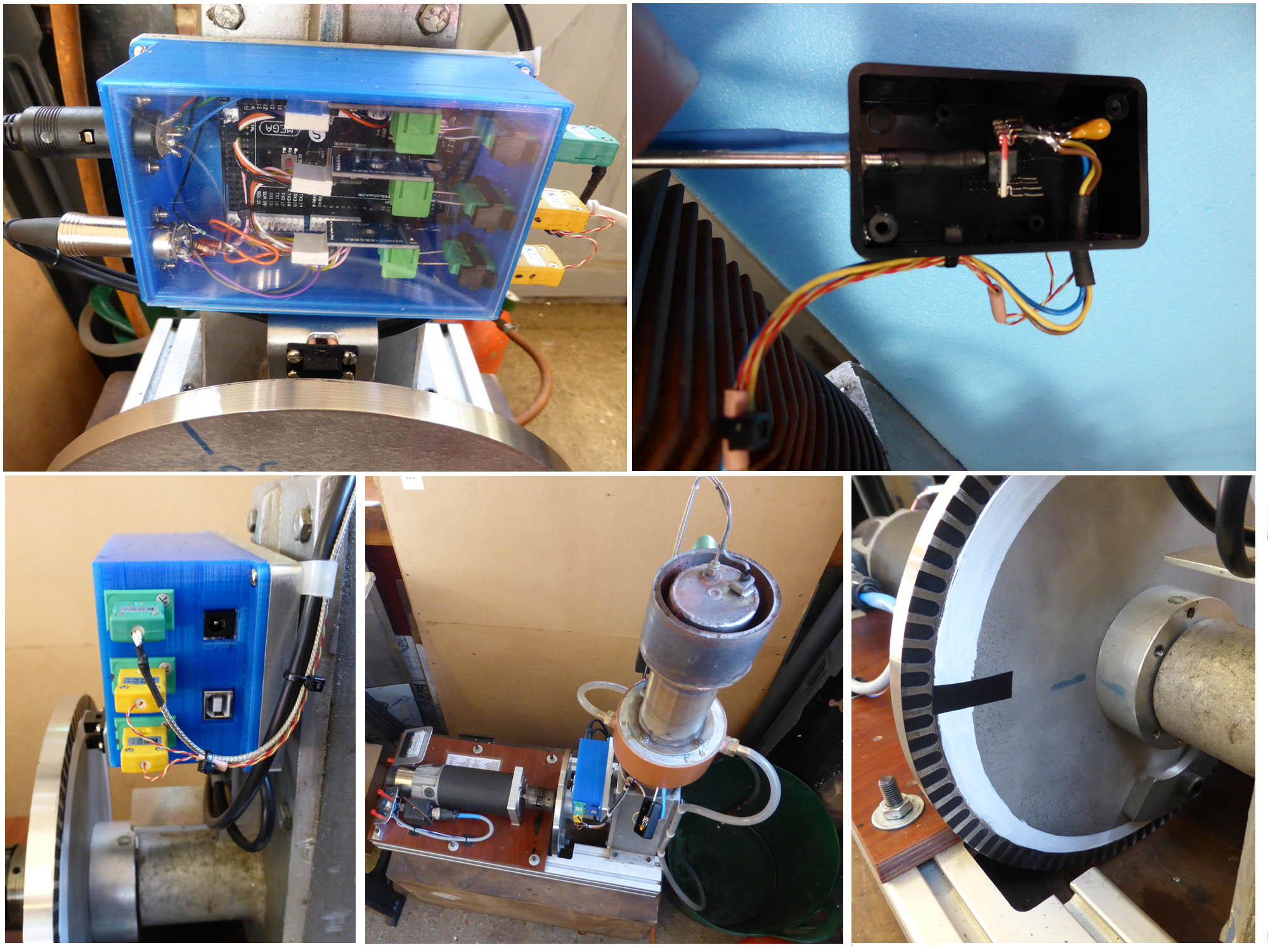
in its protective plastic box in the right hand picture.
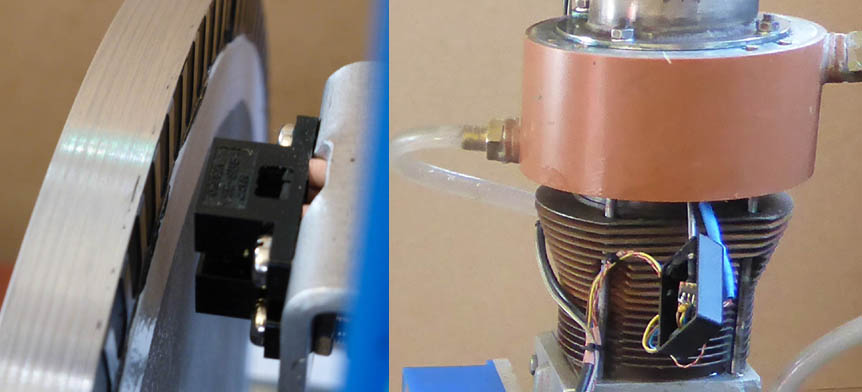
The sensors and Arduino are shown below. The pressure sensor is joined to the stainless steel pipe with
a neoprene sleeve.
Main Parts
Pressure Transducer
SSCDANN060PAAA5
Farnell 1823240
2 off
£22.34 ea
Thermocouples
tianlo_go MAX6675
Ebay
2 off
£5.28 ea
Reflective photosensors
OmronEE-SB5
RS 807-3876
2 off
£2.76 ea
Arduino Mega
iotmodules 2560 R3
Ebay
1 off
£10.97
8 way 0.1"wiring headers
pw928gts
Ebay
3 off
£2.99 (4)
Miscellaneous Parts
Enclosure for Arduino - in my case a blue 3d printed plastic box
Enclosures to protect pressure transducers - a small plastic box
Plugs and sockets for sensors - these may not be needed depending on your construction method.
Rubber sleeves to connect pressure transducers to pipe – 2mm neoprene wiring sleeves
Wire - 3 or 4 core miniature wiring cable or similar
1/8” BSP stainless steel compression fitting to be welded to the hot cap and about 200mm 1/8” stainless steel pipe.
The complete assembly is shown below.
When in operation the Arduino is powered by the 5 volts from the host PC or laptop.
The power consumption is quite low.
To collect the data a serial program like Hyperterm or Putty is needed.
The collected file can be analysed in Excel or a bespoke program.
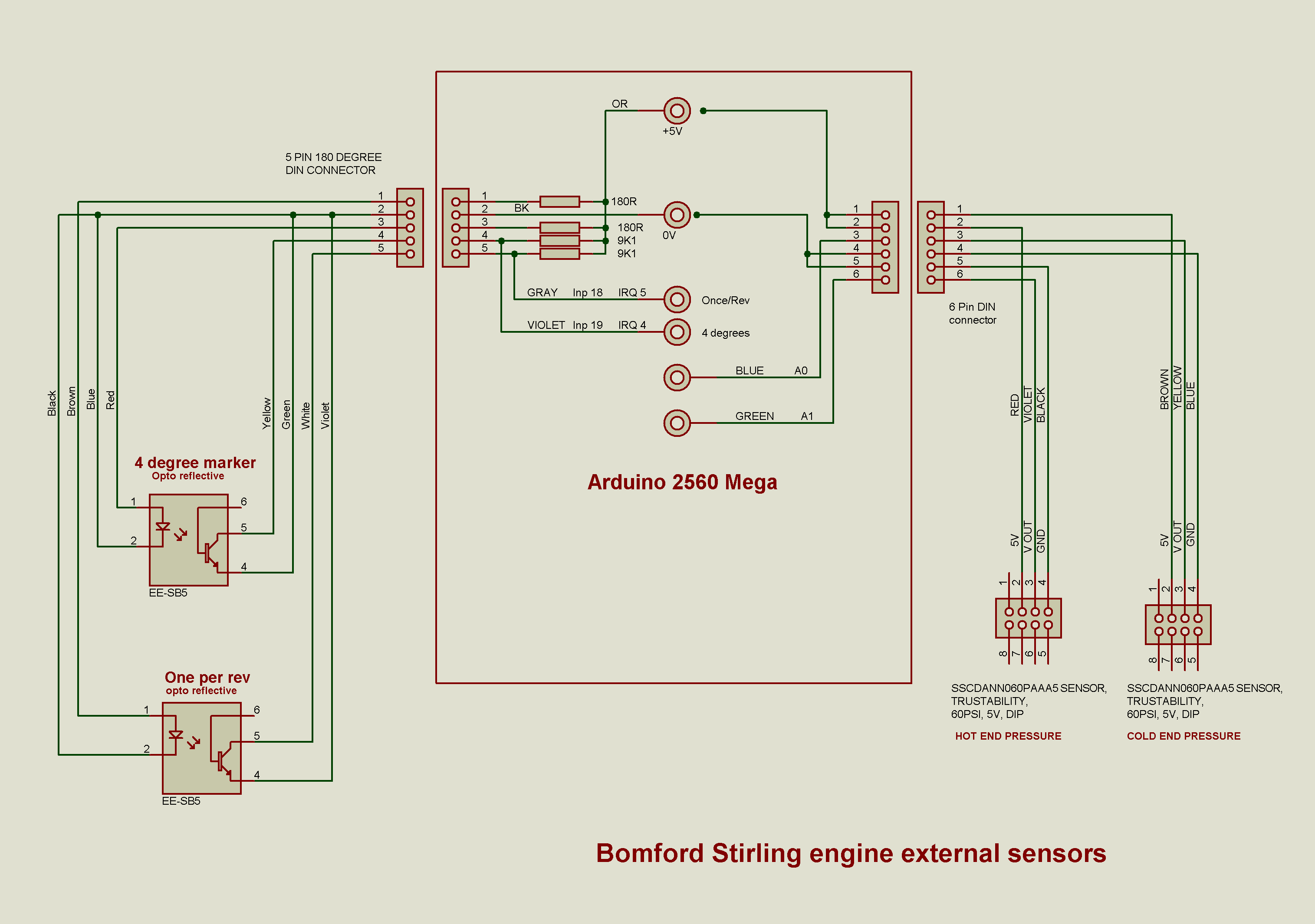
Circuit Diagrams
The circuits below show the wiring between the Arduino and the various external
sensors. The three thermocouple circuit boards are housed inside the blue plastic
box and just the braded cables from the thermocouple are external. I have used
proper thermocouple connectors for my implementation but the thermocouples can be
hardwired. If you get silly readings you have probably wired then in the wrong polarity.

Software and library files.
The text in blue is the program that sits in the Arduino Mega 2560. To get it there
you will need to get the Arduino programming interface from the internet and go from
there. This may be a completely new adventure for you, and if so will eat a good days time.
(if you can get a child to help this will speed things up!)
Please be aware that you will need to download and install a library file "max6675.h"
if you use the thermocouple system that I did. All of this is well explained on the
main Arduino website. You should be able to cut and paste the code into you Arduino 'sketch'
/* This routine used SCI to read three thermocouples whose
signals are processed by a MAX6675 conditioner.

To share the fixed call we generate three CS signals and
ignore the routine generated one
*/

#include "max6675.h"
const int coldPressure = A0;   // Analog input pin that the potentiometer is attached to
const int hotPressure = A1;    // Analog input pin that the potentiometer is attached to
const int CS_0 = 5;            // we will cycle these three pins to give three channels
const int CS_1 =  6;
const int CS_2 =  7;
const int led_pin = 13;        // diagnostic - maybe used elswhwere in OS

int thermo_DO =  2;
int thermo_CLK = 3;
int thermo_CS =  4;
int tempval=0;                // read of SCI temperature was float!
int temp_1;
int temp_2;
int temp_3;
int hot_pressure=0;
int cold_pressure=0;
int enc_pulse_pin = 19;                // encoder holes 4 degrees apart white
int once_per_rev_pin = 18;
int piston_displacement = 0;
int data_block_1_full = 0;    // handshakes to fill/release data
int data_block_1_fill = 0;
int data_block_1[368];      // 92 entries of 4 bytes for data block
int incoming_byte;
int RPM_lockout = 0;
int ptemp=0;
int do_debug = 1;
int i;
int j;
int angle_tab[90] = {      // piston displacement % *10
  1000, 999, 995, 989, 981, 970, 957, 941, 924, 905, 883, 860, 835, 808, 780,
  750, 719, 687, 655, 621, 587, 552, 517, 483, 448, 413, 379, 346, 313, 281,
  250, 220, 192, 165, 140, 117, 96, 76, 59, 43, 30, 19, 11,  5,  1,
  0,  1,  5, 11, 19, 30, 43, 59, 76, 95, 117, 140, 165, 192, 220,
  250, 281, 313, 345, 379, 413, 448, 482, 517, 552, 587, 621, 654, 687, 719,
  750, 780, 808, 835, 860, 883, 904, 924, 941, 957, 970, 981, 989, 995, 999
};

unsigned long old_time;
unsigned long new_time;
unsigned long this_time;
unsigned long RPM = 0;

volatile int four_degree = 0;
volatile int opr = 0;      // value of once per rev pin
volatile int piston_position = 0;
MAX6675 thermocouple(thermo_CLK, thermo_CS, thermo_DO);

void setup() {
  pinMode(CS_0, OUTPUT);
  pinMode(CS_1, OUTPUT);
  pinMode(CS_2, OUTPUT);
  pinMode(led_pin, OUTPUT);
  pinMode(enc_pulse_pin, INPUT);
  pinMode(once_per_rev_pin, INPUT);
  attachInterrupt(4, enc, RISING);
  for (i = 0; i < 277; i = i + 1) {          // clear array
    data_block_1[i] = 0;
  }
  RPM_lockout = 0;
  do_debug=1;
  new_time = millis();
  old_time = millis();
  Serial.begin(9600);
  Serial.println("MAX6675 test");
  delay(100);  // wait for MAX chip to stabilize
}

void loop() {
      while(Serial.peek() < 0) run_debug();     // no chars are in inbuff
      run_block();
}

 void run_block(){
   while(true){
          if (Serial.available() > 0) {
                   incoming_byte = Serial.read();       // read the incoming byte but dont use
                   data_block_1_fill = true;            // handshake
                   if (data_block_1_full = true) {
                           for (j = 0; j < 359; j = j + 4) {     // blocks of four bytes
                               Serial.print(data_block_1[j]);
                               Serial.print(",");
                               Serial.print(data_block_1[j + 1]);
                               Serial.print(",");
                               Serial.print(data_block_1[j + 2]);
                               Serial.print(",");
                               Serial.print(data_block_1[j + 2]);
                               Serial.print(",");
                           }
                           Serial.print("  RPM=");
                           Serial.print(RPM);
                           Serial.print("  Hot temp=");
                           Serial.print(temp_1);
                           Serial.print("  Gas temp=");
                           Serial.print(temp_2);
                           Serial.print("  Cold temp=");
                           Serial.print(temp_3);
                           Serial.println("   END");
                           data_block_1_full = false;
                           data_block_1_fill = false;
                    }
              }
       }
 }


  // **********************  INTERRUPT ROUTINE EVERY ENCODER PULSE ****************************
  void enc(){                                // interrupt call every 4 degrees of flywheel
    opr = digitalRead(once_per_rev_pin);
    if (opr == HIGH) {                     // Top dead centre of PISTON
      four_degree = 0;                     // restart angle count
      old_time = new_time;
      new_time = millis();
      this_time = new_time - old_time;      // ms for this rev
      RPM = 60000 / (this_time);            // TO REVS/MIN
    }
   read_temps();
 //  hot_pressure = analogRead(hotPressure);
 //  cold_pressure = analogRead(coldPressure);
   piston_displacement = angle_tab[four_degree];

    /*  Fill data block 1 comprising
     four_degrees,hot_pressure,cold pressure, piston_displacement,
     90 times (0-89)
     */
    if (data_block_1_fill = true) {
      i = 4 * four_degree;  // only do once per
      data_block_1[i] =     four_degree;
      data_block_1[i + 1] = hot_pressure;
      data_block_1[i + 2] = cold_pressure;
      data_block_1[i + 3] = piston_displacement;
    }
    if (four_degree >= 90) {
      data_block_1_fill = false;    // handshake
      data_block_1_full = true;
    }
    ++four_degree;        // note array counts from 0
  }

void read_temps(){
 //      ** Read thermocouple 1 **
   digitalWrite(CS_0, LOW);
   digitalWrite(CS_1,HIGH);
   digitalWrite(CS_2,HIGH);
   temp_3=thermocouple.readCelsius();
   digitalWrite(CS_0, HIGH);

 //      ** Read thermocouple 2 **
   digitalWrite(CS_0,HIGH);
   digitalWrite(CS_1, LOW);
   digitalWrite(CS_2,HIGH);
   temp_2=thermocouple.readCelsius();
   digitalWrite(CS_1, HIGH);

//      ** Read thermocouple 3 **
   digitalWrite(CS_0,HIGH);
   digitalWrite(CS_1,HIGH);
   digitalWrite(CS_2, LOW);
   temp_1=thermocouple.readCelsius();
   digitalWrite(CS_2, HIGH);

}
/* the pressure transducer has a range of 0.5 to 4.5 volts
   this covers the range of 0 to 60 psi absolute.
   we will rescale this variable to 0 to 600 counts
   The adc has span 0f 1024 for 5 volts.  */
void read_pressures(){
   ptemp = analogRead(hotPressure);
   constrain (ptemp, 103,922);
   hot_pressure = map(ptemp,102,922,0,600);
   ptemp = analogRead(coldPressure);
   constrain (ptemp, 103,922);
   cold_pressure = map(ptemp,102,922,0,600);


//   hot_pressure = analogRead(hotPressure);
//   cold_pressure = analogRead(coldPressure);
}

void run_debug(){
      read_temps();
      read_pressures();
      Serial.print("  Hot temp=");
      Serial.print(temp_1);
      Serial.print("  Gas temp=");
      Serial.print(temp_2);
      Serial.print("  Cold temp=");
      Serial.print(temp_3);
      Serial.print("  Hot Pressure=");
      Serial.print(hot_pressure);
      Serial.print("  Cold Pressure=");
      Serial.println(cold_pressure);
      delay(500);
}
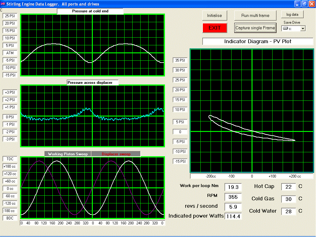
Conclusion
Much interesting and informative data has been collected from this engine
and a greater understanding of the design compromises has been reached.
The total cost is not too great (compare with a fill of petrol), and
it is not too difficult for a practical person to undertake.
It is possible that I have not covered some aspects in sufficient detail for individual
endeavours, and I am happy to enter into correspondence if needed at
dennis@cowdery-cowdery.demon.co.uk
Dennis Cowdery