I learnt of this engine, at an International Stirling Engine Conference, some years ago. In discussions with Jim Senft he referred to it a Lamina flow engine, in US patents it is usually called an acoustical heat engine. Jim's explanation seemed, at the time, clear however on my return to the UK it was evident I had not fully understood the theory since I failed to get an experimental engine to work! Subsequent research unearthed patents and other literature dating back to the 1950's, these clarified the working cycle of this type of engine.
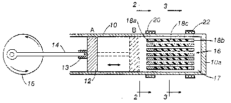
The schematic drawing, below, taken from a US patent granted in 1984 is for a heat pump. There are two heat exchangers 22, the hot exchanger, and 20 the cold exchanger. 18 is the regenerator stack. In practice the layout is not so simple as a true acoustical heat engine requires a resonate gas circuit.
After a lot of experimentation I found the solution to turning this into a motor was simply a matter of applying heat to the end of the regenerator stack nearest the piston.
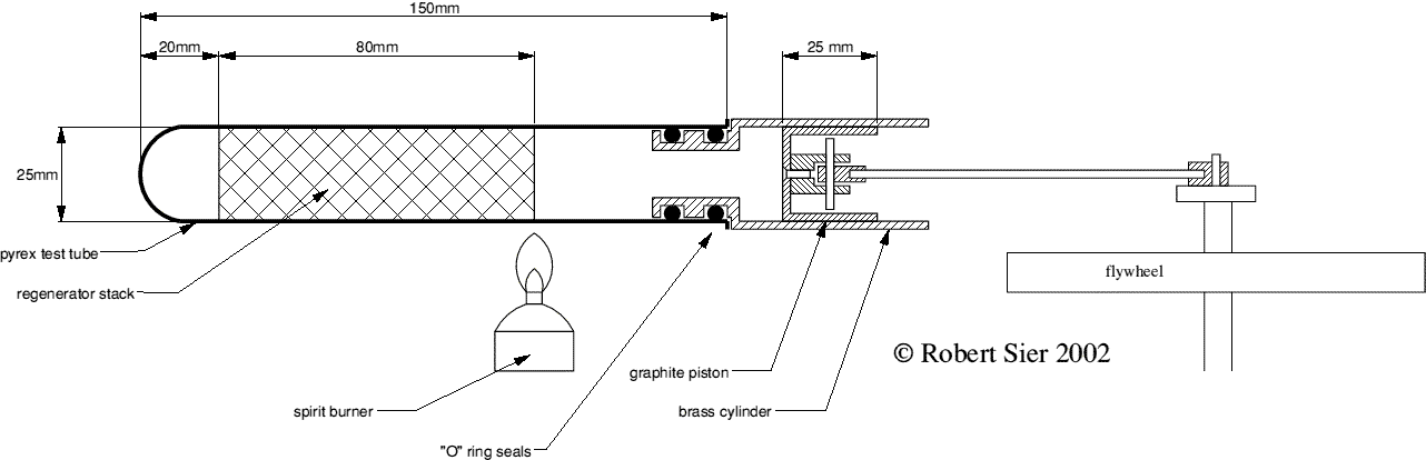
This is a very simple engine to make since it has, effectively, only one moving part--the piston. The piston sends a pressure wave down the heated tube. The engine bears some resemblance to the thermoacoustic engine but differs in not using resonate tubes. Also unlike the Tailer "thermal lag" engine its operation requires a regenerator stack.
The drawing should be self explanatory, the main parts of the engine are :
Heater tube I use Pyrex glass tube to demonstrate the absence of moving parts in the heater tube, although stainless steel could also be used.
(Click on figure to view enlarged drawing)
Regenerator The regenerator stack is made from a stainless steel pot scourer, some adjustment of the location of the regenerator along the tube may be required for optimum output. Part of the regenerator also acts as the hot heat exchanger.
Piston & cylinder. The piston is of graphite with a honed and polished brass cylinder, removing the need for lubrication.
I made the stroke of the piston variable. It will be found that the power of the engine increases with the stroke, this is because larger volumes of air are pulsed through the heat exchanger.
The burner A small spirit burner is all that is required, too much heat will stop the engine. The flame should be placed at the end of the regenerator stack nearest the piston.
The flywheel This needs to be reasonably heavy but this is dependant on the level of compression the engine operates at.
With the engine running it will be found that the closed end of the displacer remains cold whilst the cylinder end warms up. For lengthy running the power cylinder would need be fitted with cooling fins.
Please note
© Robert Sier. 2002