Roy Darlington
Roy Darlington


STIRLING SILVER.
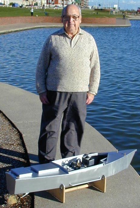
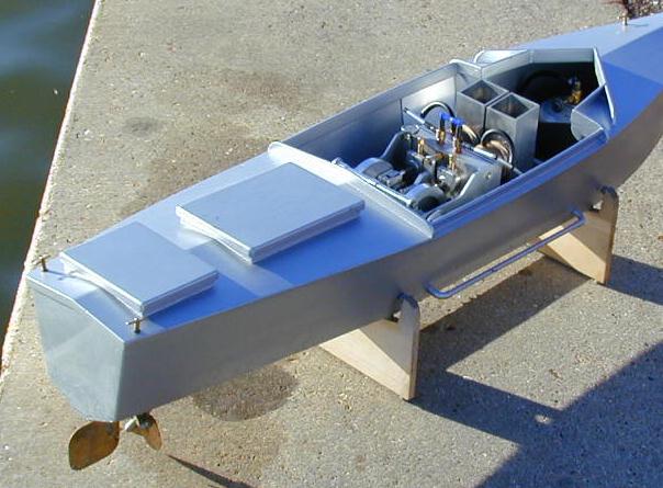
Stirling Silver is the name given to my latest project. This is a 50" scratch built hull powered by a twin cylinder Stirling engine of my own design. This boat is radio controlled (Twin channel), digital proportional control system. It has forward, reverse, and neutral all from one control this also covers a variable speed, by gentle use of this same control. The remaining control on the transmitter is used to control the rudder. The engine runs at constant speed. This gives perfect control of the boat on the water. There is no need for variable pitch props, or kitchen type rudders. The engine is water-cooled and the boat has its own water tank with a sealed system. The water is pumped with a battery operated electric pump. The water is pumped through the engines main block and two water jackets. It is then pumped through two external pipes, using the cold water of the lake to cool the water before returning to the tank. The electric pump makes more noise than the main engine.
The engine runs at 1,200 R.P.M. with an estimated power of 12 watts it is very difficult indeed to stop the engine by holding the main shaft (1/4"Dia.) with the fingers. The main cylinder block is 5 ¾" wide x 1 ¾" thick x 3 ¾" high and is made up of four plates of aluminium, 3/8" thick, 3/16" thick, 3/4" thick and 1/4" thick. The cylinder block is made this way so that water channels and air channels can be milled into the plates and then assembled with gaskets between the plates pinned and bolted together to become a solid block with all the air and water channels internal. The displacer cylinders and displacer pistons are both made of stainless steel (drawn.) The displacer cylinders are 3 9/16" long x 1 3/8" dia. The power cylinders are made of Duralumin, locktighted into bored holes in the cylinder block. The power cylinders are 1 1/8" bore and 1 1/2" long. The power pistons are of the leather cup washer type and apart from being ideal for Stirling engines, it allows for a very short power cylinder. I was aiming for the smallest size and low weight for the engine. The stroke of both Power and Displacer pistons are 7/8". A modified Ross linkage has been used to link the Pistons, instead of using a swinging lever I have used a straight guide rod. This gives nearly parallel motion with very little side thrust on the pistons. I used this idea on my first twin cylinder boat engine and found it worked very well.
The sideplates of the engine are made of 1/8" thick aluminium. If I were making another engine of this type I would use 3/16" or even 1/4" thick. When the engine first ran, the side plates flexed. I had to stiffen the engine by adding aluminium angle to the base plate and increase the size of the main bearings, main shafts and bearing housings. After all of that it still needed a tie bar across the top of the engine. I had underestimated the forces involved. It now runs very smoothly and starts in a few seconds from cold. You only have to turn it over compression and away it goes.
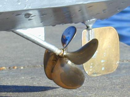
The transmission from engine to prop. shaft is via a friction drive and a universal drive.
The friction drive is as used by a very good friend of mine Peter Beier (Austria). Peter has used this type of drive on several Stirling powered boats he has made, and was kind enough to pass on to me all the information on this type of drive. Having put it to the test I can confirm it is very simple but very effective for model boat propulsion. The engine has two flywheels, one on each side of the engine both rotating in the same direction, at 90 to the flywheels is a rubber faced disc. In the neutral position the disc has a clearance of 2mm from the flywheels. In the forward position the friction disc is pressed against one flywheel by a spring loaded arm on the servo. The engine is always running full speed but you can select any speed you want by control pressure on the friction disc.
To reverse you engage the disc on to the other flywheel and reverse at full speed if you need to. The friction disc rotates on a shaft running in two ballraces in a housing that pivots. The universal coupling is mounted on the other end of this shaft and takes the drive to the prop shaft.
The engine is gas fired by twin burners of my own design. In tests recently conducted I have registered temperatures of over 900 C inside the hot end, and a flame temperature of over 1506 C a short distance above the burner. I did have a cunning plan to pump the hot water from the engine over the gas tank and back in to the system. The idea being the hot water would raise the gas pressure and the low temperature of the gas cylinder would help to cool the cooling water temp. I did try it but the gas cylinder rusted, and it complicated the removal of the gas cylinder. As it is, I can change the gas cylinder in less than a minute and this is important at the lakeside. The engine is only held in the boat with three knurled nuts and can also be removed from the boat in less than a minute.
The hull is a test bed for the engine, it has no other purpose. It was more or less built around the engine and the necessary ancillary components, gas tank, radio, batteries, water tank, etc.
It is mainly built of plywood, the bottom of the boat is shaped it is not flat bottomed. The screws that hold the engine were araldited into the lower deck. The engine was then fitted with all the other components and I could then see where to fit the bulkheads. Once I was sure that I had room for everything the bulkheads were cut and fitted.
Everything was then re-assembled and the engine prop shaft servos and radio were tested in position. All was well, so the sides and top deck were added, sanded and painted silver. I was very pleased with the look of the hull when complete and it is far stronger than it need be. The bow is made from laminated ply and was shaped when glued to the hull, this took a complete day to carve. (You cannot put a 50" hull in the vice to hold it!) I would use hard balsa wood if I make another. The other thing I would change is the angle of the prop shaft. The stern would be angled to allow the prop shaft to be at a less acute angle. You live and learn! There is no drawing for the engine or the hull; the linkage for the engine was drawn on scraps of paper so that I could get the stroke I wanted and the shape of the bulkheads were also made like this, drawn directly on to the plywood. Before making the hull I had a chat to Richard White, a close friend who is a professional boat designer in Norway. I was in doubt what the displacement would be. Armed with the size of the hull and the weights of all the components he soon told me where the water line would be. He also gave me a few tips on the shape to aim for. The performance came up to expectation. The engine has now run well over a hundred hours, with no trouble at all and has been on the water for approx. five hours. It glides along at just over 1 metre per second and for a 28 cc Stirling engine in a rather large and heavy hull it is quite pleasing.
I am now building a single cylinder engine to go in Stirling Silver Mk 2. The hull was designed and built by Richard White.
So, watch this space!!!
ROY DARLINGTON